Irricloud Wiring Diagrams
Wiring the Irricloud system is relatively straightforward. We first describe wiring the headnode and first extender board, then wiring additional extender boards and sensors, if present.
Headnode/Extender Wiring
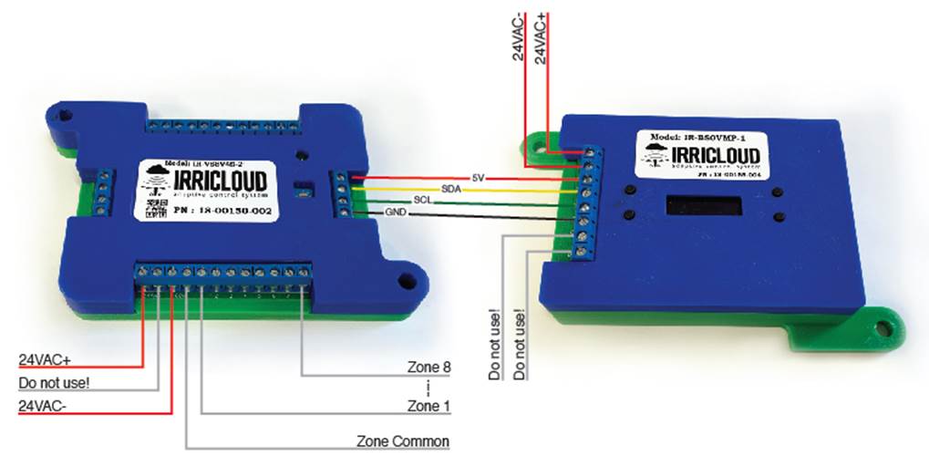
The headnode can be wired to either (but NOT both) a 24VAC power source or a 12VDC-24VDC power source. This allows it to be powered by solar panels or more traditional 24VAC zone transformers. The top two terminal blocks (both labeled AC) are used for the two legs of the 24VAC power source and the bottom two terminal blocks (labeled +/-) are connected to the positive and negative leads on the DC power source. The intermediate 4 terminal blocks (labeled (top to bottom) 5V, DA, CL, GN) provide the control wiring to the zone extender boxes and wire to the corresponding Zone Extender labels (5V, SDA, SCL, GND). Power for the headnode and control of the extenders is completely isolated from power for the zones.
When wiring the zones, the leftmost terminal (labeled 24VAC) is wired to one leg of the customer supplied 24VAC power adapter. This is typically labeled 24VAC+ and the other leg of the power adapter is labeled 24VAC-, though frequently there are two wires of the same color with no labeling. The second from left terminal is a short circuit to the SAME 24VAC+ connection so it is important that 24VAC- wire is NOT connected to this terminal. If it is, the power adapter will short circuit and likely need to be replaced.
The 24VAC- wire (2nd leg of the 24VAC power adapter) should connect to the third terminal from the left. The third and fourth terminals are also shorted together and used as a common for the substation.
AC valves typically have two wires coming from them. For each valve, one of their wires should be connected to a zone position (1..8) and all of the remaining wires are Zone Common and should be wired together and connected to the fourth from left terminal labeled COM.
The image below shows a headnode powered by 24VAC power wired to a single extender.
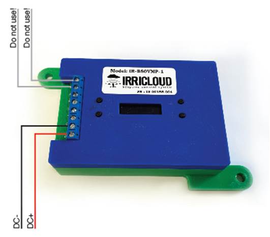
If a headnode is powered using a DC power source, then it is wired as shown in the image below. The wiring for the extender board connected to the headnode is unchanged, regardless of whether the headnode is AC or DC powered. For DC powering, the acceptable voltage range is 10VDC to 24VDC.
Additional Extender Wiring
Additional zone extenders can be wired into the controller by simply daisy chaining them together using the four (5V, SDA, SCL, GND) control wires from one extender to the next. The 24VAC+ from one extender should connect to the 24VAC+ on the next extender and also the COM wire on one extender should connect to one of the two COM terminals on the second extender.
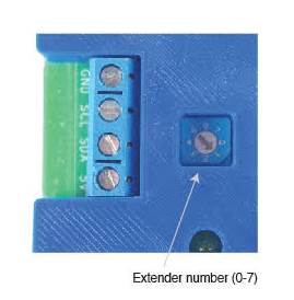
Each extender module must also be assigned a unique number between 0 and 7 with the first extender having number 0, the second extender having number 1, etc. The number can be changed by turning the dial near the LED with a small screwdriver. If two extenders have the same number, the system will not work.
Extender Sensor Wiring
On the opposite side of the zone wiring terminals are the sensor wiring terminals. There are 12 terminals supporting 4 sensors with three wires for each sensor:
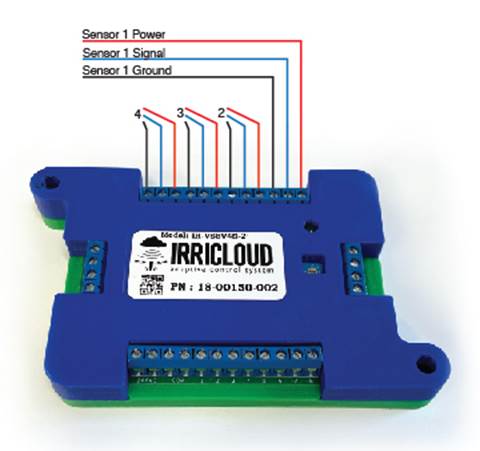
The rightmost wire in a block of three is the 5V power for the sensor (sometimes labeled vcc or +). One position to the left is the signal wire for the sensor (sometimes labeled out and typically a color other than red, black or gray), and one position to the left of the signal wire is the GND wire (sometimes labeled -). The rightmost block of three terminals is for sensor position one, and the leftmost block of terminals is for sensor position 4. Most sensors will use all three wires.