Sensor Configuration
The Irricloud system has support for many different styles of sensors that can be used to collect data and even control the operation of programs resulting in the ability to control watering based on sensor outputs or to take actions when leaks are detected.
Initial sensor types include: Temperature, Leak Detectors, Moisture, and Dry Contacts. Temperature sensors collect temperature data, Leak Detectors identify leaks and clogs in the system, and Dry Contacts can be used to take actions based on transitions (like motion detection). Sensors can also be combined to logically produce a new kind of sensor that may trigger under some restricted conditions like when a moisture sensor is low AND it is not between 10AM and 4PM.
Sensors are created, viewed, and modified by clicking on the Sensors button located on the Home Page once you have logged onto the system.
![]()

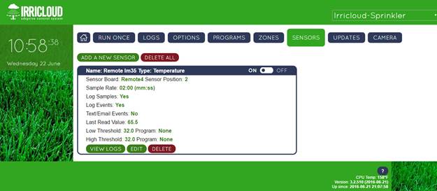
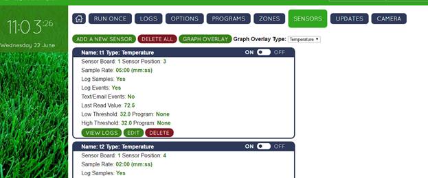
After clicking on the Sensors button you will see all of your existing sensors. Over 75 sensors can be tracked so you shouldnt worry about running out. Sensor descriptions and data will persist across reboots and power outages because they are saved in non-volatile memory; no battery backup is required to keep your sensor configuration.
Creating a Sensor
The following steps will describe how to incorporate a new sensor into the system. Modifying an existing sensor is similar to creating a new sensor, except the information from the existing sensor is already populated into the editing window.
Each sensor must have a unique Sensor Name assigned to it. We create a new sensor by clicking the Add a New Sensor button.
A sensor editing window will show up where the various characteristics of the sensor can be filled in.
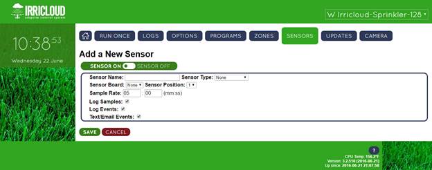
The Sensor On/Sensor Off button enables/disables your sensor. If a sensor is disabled, it is effectively ignored for watering, but the underlying data is maintained in case you wish to re-enable it in the future. A sensor that is enabled is colored green while one that is disabled is rust colored like the CANCEL button shown above.
Each sensor requires a unique name and is assigned a type. The sensor board is either the number of the Valve Sensor Module (VSM) (1-8) or the unique name of a connected remote radio module that has sensors attached. The sensor position is the set of terminals where the sensor is wired to the sensor board. There are generally four available terminals for VSM sensors (1-4), and two available terminals for radio based sensors (1-2).
Sample Rate is the frequency at which the sensor is checked. For remote radio attached sensors, the frequency of checking sensor data is limited to no more than once per minute.
Log Samples is checked when the sampled value should be logged for recording purposes; the amount of logging is controlled on the Options page.
When Log Events is checked, if a sensor exceeds a specified threshold the data will be logged.
Text/Email Events is checked if a text message or email message should be sent when a sensor exceeds a specified threshold.
Thresholds are determined by sensor type. Below is an example temperature sensor that will send a text or email whenever the temperature drops below 32F, when it returns back to the normal range of 32F-40F, and when the temperature rises above 40F.
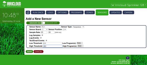
Note also, that a program can be executed when a sensor threshold is crossed. In the picture above, no program is selected, but it would be possible to start a program which turns on zone 4 (type Indefinite Watering) when the Low Threshold is crossed, and run a different program that would turn off zone 4 (type Fixed Ban with Stop) when the High Threshold is crossed.
Sensor Logs
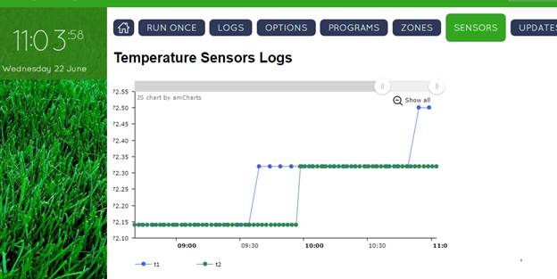
It is possible to view the sensor data graphically by selecting VIEW LOGS for the given sensor.
![]()
The graphical data can be zoomed in or out or dumped to a .csv file for further processing.
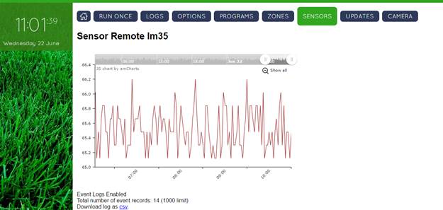
If multiple sensors of the same type are available, then they can be graphed together by clicking on GRAPH OVERLAY and selecting the appropriate sensor type.
Leak Detector Sensors
Flow meters can be used to identify leaks or clogs in a system. In general, the system learns what the expected flow is under different configurations and then identifies a leak when there is excess flow relative to expectations or a clog when there is insufficient flow relative to expectations.
The leak detector has a Sensitivity which determines how accurately the flow must match expectations before sending an alert. In the example below, if the flow is less than 90% of what is expected (or more than 110% of what is expected) a clog (leak) will be texted or emailed.
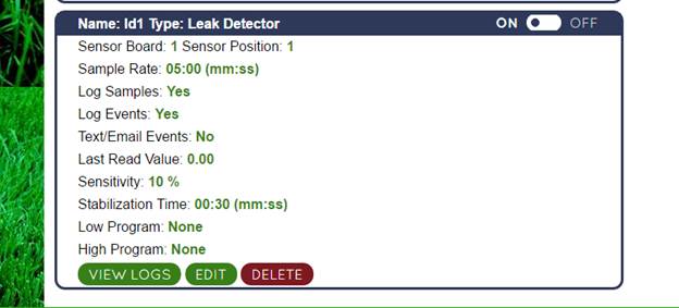
The Stabilization Time represents an interval (30 seconds in the above example) after a zone is turned on or off where flow expectations are ignored. This allows the system to settle down during transitions to avoid excessive alerts.